
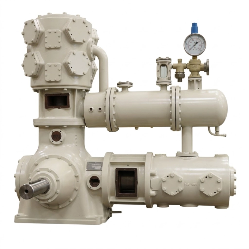
LW-9/8.7-29 Oil-Free Air Booster Compressor
Optimize your plant with the LW-9/8.7-29 Oil-Free Air Booster Compressor. Efficiently amplifies 8.7 bar to 29 bar at 540 Nm³/h for heavy industry.
1. The Macro-Economics and Strategic Value of Pneumatic Boosting
Within the highly complex architecture of modern industrial plant design, energy consumption dictates ultimate profitability. Compressing atmospheric air from 1 bar all the way to 29 bar requires an immense amount of electrical power. In massive manufacturing facilities, 80% to 90% of the automated pneumatic machinery (such as pneumatic cylinders, automated sorting gates, and standard CNC tooling) only requires a baseline pressure of roughly 7 to 8.5 bar. However, highly specific, critical processes—most notably the injection stretch blow molding of PET polymer bottles, or high-wattage fiber laser cutting assist gas—strictly demand 29 bar of highly concentrated kinetic force to operate successfully.
If an entire facility’s centralized compressor room was configured to generate 29-bar air purely to satisfy the PET blow molding lines, and then artificially regulated down to 8 bar for the rest of the plant, the thermodynamic and financial waste would be catastrophic. The factory would be burning hundreds of thousands of dollars annually in wasted electrical energy compressing air to an extreme pressure that the vast majority of the plant does not utilize. This is the exact macroeconomic paradox that the LW-9/8.7-29 Oil-Free Air Booster Compressor was engineered to solve.
The strategic deployment of the LW-9/8.7-29 creates a highly intelligent, split-utility architecture. Your facility continues to run its massive, highly efficient low-pressure rotary screw compressors to provide 8.7-bar baseload air to the entire plant. The LW-9/8.7-29 is strategically installed directly adjacent to your high-pressure PET packaging or laser cutting lines. It dynamically ingests 9 Nm³/min of this 8.7-bar baseload air and aggressively “boosts” it up to the critical 29 bar required by the specific downstream equipment. Because the booster begins its compression cycle already fed with dense, pre-compressed 8.7-bar air, the mechanical workload and electrical consumption required to reach 29 bar are slashed by over 60% compared to compressing from zero. Furthermore, maintaining strict ISO 8573-1 Class 0 oil-free purity throughout this boosting phase guarantees that your high-value consumer packaging remains entirely free from explosive or toxic hydrocarbon contamination.
Figure 1: The LW-9/8.7-29 Heavy-Duty Booster Assembly. Designed to physically intercept standard utility air and mechanically amplify it to 29 bar. Notice the robust, heavy-walled structural piping required to handle the amplified dynamic discharge forces.
2. Exhaustive Technical Specifications & Operating Envelope
Precision fluid dynamics scaled to a 29-bar (2.9 MPa) terminal pressure at a volumetric throughput of 540 Nm³/h mandates that the booster’s internal structural integrity is mathematically calibrated for high-density gas ingestion. Because the intake air is already compressed to 8.7 bar, it is significantly denser than atmospheric air, creating highly unique dynamic rod loads on the crankshaft and extreme impact stress on the intake valves. The following comprehensive technical parameters deeply define the highly efficient, strictly oil-free operational envelope of the LW-9/8.7-29 model.
| Technical Parameter | Nominal Value / Engineering Specification |
|---|---|
| Model Designation Architecture | LW-9/8.7-29 (High-Efficiency Oil-Free Booster Series) |
| Approved Compression Medium | Pre-treated Factory Process Air, Nitrogen (N&sub2;) Base Gas |
| Volumetric Flow Rate (Capacity) | 9.0 Nm³/min (540 Nm³/hour) – Continuous Baseload Duty |
| Mandatory Suction (Inlet) Pressure | 0.87 MPa (8.7 bar / approx. 126 psi) |
| Target Terminal Discharge Pressure | 2.9 MPa (29.0 bar / approx. 420 psi) |
| Compression Ratio (Total) | Highly Efficient ∼3.33:1 Thermodynamic Amplification |
| Kinematic Frame & Layout | LW-Type (Compact footprint, vibration-dampened geometry) |
| Air Purity Certification | ISO 8573-1 Class 0 (100% Absolutely Oil-Free via distance piece isolation) |
| Thermal Management Protocol | High-Efficiency Industrial Water Cooling System |
| Primary Sealing Material | Self-Lubricating Glass-Fiber/Carbon Reinforced PTFE Matrix |
| Main Drive Motor Power | Typically 75 kW to 90 kW (Significantly lower than base compression) |
| Manufacturing Compliance Codes | API-618 (structural spacing), CE Machinery Directive, ASME Section VIII |
Intake Air Quality Advisory: While the LW-9/8.7-29 is a strictly oil-free machine, its internal PTFE seals and PEEK valves absolutely rely on the purity of the incoming 8.7-bar baseload air. If your primary factory screw compressors are oil-injected, the EPC contractor must heavily filter the 8.7-bar air through a rigorous desiccant drying and multi-stage coalescing filtration skid before it enters the booster. Ingesting oil aerosols or heavy liquid water condensate from the primary plant grid will rapidly foul the high-pressure booster valves and degrade the advanced PTFE composite sealing rings.
3. The Fluid Dynamics and Thermodynamics of Dense-Gas Amplification
Thermodynamically, compressing gas that is already pressurized to 8.7 bar poses entirely different engineering challenges compared to compressing atmospheric air. At 8.7 bar, the structural density of the gas is roughly nine times greater than air at sea level. When the massive piston of the LW-9/8.7-29 draws in this highly dense pre-compressed mass and forcefully reduces its physical volume to achieve 29 bar, the kinetic behavior of the oxygen and nitrogen molecules is extremely aggressive. The total pressure ratio is approximately 3.33:1 (29 bar divided by 8.7 bar). According to the foundational laws of adiabatic thermodynamics, this specific ratio is mathematically ideal for highly efficient, extremely powerful single-stage or specialized two-stage mechanical amplification.
Because the pressure ratio is carefully controlled, the violent spike in kinetic molecular heat—which normally plagues high-pressure compressors attempting massive pressure jumps—is inherently mitigated. However, due to the extreme physical mass of the dense gas being compressed, immense thermal energy is still generated during the stroke. To mathematically enforce a strict thermal safety barrier and prevent the self-lubricating PTFE friction seals from degrading under the intense frictional heat, the LW-9/8.7-29 is equipped with a heavily fortified shell-and-tube thermal management architecture.
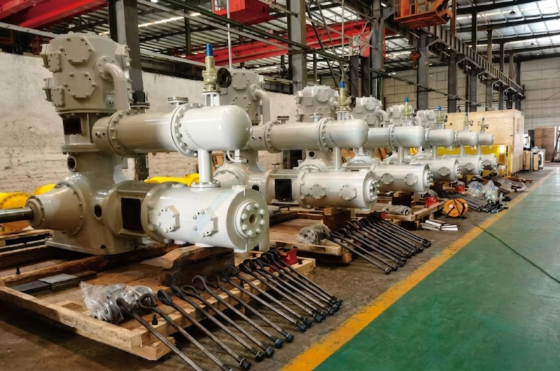
Figure 2: Thermodynamic Thermal Control. The massive heavy-wall cylinders are deeply encased in advanced industrial water-cooling jackets. Chilled water constantly aggressively strips away the adiabatic heat generated by boosting the highly dense 8.7-bar air into its final 29-bar state, mathematically preserving the integrity of the internal non-metallic seals.
A continuous, high-volume flow of chilled, chemically softened industrial facility water is forcefully circulated through both the heavy cast-iron cylinder water jackets and the massive downstream aftercooler heat exchanger. As the hot 29-bar-bound air exits the terminal valve, the cold water rapidly strips away the intense kinetic heat. This deeply intelligent thermal cooling ensures that the air discharged directly to your sensitive PET blow molding equipment or downstream receiver tanks is dense, highly stable, and strictly cooled to below 45°C. This critical thermal control drastically reduces the electrical load on the primary induction motor and vastly extends the operational MTBF (Mean Time Between Failures) of the entire pneumatic system.
4. ISO 8573-1 Class 0: Absolute Oil-Free Booster Sealing Architecture
Amplifying gas to 29 bar presents a severe contamination paradox if standard lubricated booster technology is utilized. If liquid hydrocarbon oil is injected into the booster cylinder to seal the high-pressure gap, it will rapidly vaporize under the heat of compression. Exposing downstream applications—such as blowing high-purity pharmaceutical-grade PET bottles, or pushing laser cutting assist gas through extremely sensitive, million-dollar optic lenses—to 29-bar oil aerosols will instantly and permanently ruin the product and shatter the optics.
To uncompromisingly secure the highly coveted ISO 8573-1 Class 0 (zero oil) certification, the LW-9/8.7-29 booster entirely abandons liquid lubrication within the pressurized gas path. The heavy-duty pistons are sealed utilizing highly proprietary, extremely rigid piston rings, heavy rider bands, and primary rod packing sets fabricated from virgin Polytetrafluoroethylene (PTFE). To withstand the aggressive friction and dense-gas resistance of 29-bar boosting, the polymer matrix is aggressively alloyed with aerospace-grade milled glass fibers, high-temperature carbon graphite, and specialized structural bronze powder. As the massive piston oscillates, a microscopic layer of the PTFE blend permanently bonds to the highly polished, hardened stainless steel cylinder walls, creating a flawless, frictionless hermetic seal that contains the 29-bar air without any liquid assistance.
However, the heavy forged crankshaft and crosshead bearings located in the lower mechanical crankcase strictly require a pressurized flood of standard liquid hydrocarbon oil to survive the continuous 90 kW mechanical load. To absolutely guarantee this oil never migrates upward into the pure 29-bar air stream, the machine is constructed utilizing deeply extended, highly ventilated API-618 Type-B or Type-C Distance Pieces. These act as open-air physical isolation structural chambers, vastly separating the oily lower crankcase from the ultra-dry boosting cylinders. Specialized heavy-duty scraper rings wipe the massive piston rod entirely dry as it leaves the lower casing. Because of this large physical open-air gap, it is physically, mechanically, and mathematically impossible for crankcase oil to travel upward and breach the 29-bar clean air zone, ensuring decades of perfectly pure downstream output.
5. The Physical Advantages of the LW-Type Kinematic Framework
Unlike primary multi-stage compressors that require massive, sprawling horizontally-opposed footprints, booster compressors are fundamentally designed to be deployed directly adjacent to the machinery they are amplifying (point-of-use deployment). Space in modern automated packaging halls or advanced CNC fabrication floors is incredibly expensive and highly restricted.
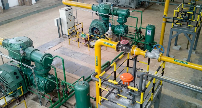
Figure 3: Real-world operational deployment of the highly efficient LW-Type architecture. The vertical or acute-angle alignment of the compression cylinders drastically minimizes the total square footage required, allowing the booster to be installed directly next to the critical PET blow molder.
To conquer spatial limitations without compromising heavy-duty mechanical stability, the LW-9/8.7-29 utilizes a highly compact, hyper-rigid LW-Type Kinematic Architecture. The heavy-duty compression cylinders are arranged in a specific vertical or tight L-shaped/W-shaped geometric configuration directly above the central cast-iron crankcase. This brilliant arrangement mathematically minimizes the overall horizontal footprint of the steel skid by over 40% compared to traditional symmetrical designs.
Furthermore, despite the compact footprint, the internal reciprocating masses (the heavy steel pistons, cast crossheads, and thick connecting rods) are precisely weight-matched and geometrically counter-balanced down to the exact gram by our mechanical engineers. This sophisticated internal balancing severely limits the destructive low-frequency dynamic vibrations generated when violently pushing against the 29-bar aerodynamic resistance. The final result is a highly potent ~90 kW point-of-use booster that operates with uncanny smoothness, fiercely protecting the structural integrity of the surrounding delicate automated packaging robotics.
6. Strategic Industrial Synergies: Localized Boosting & Advanced PET Packaging
As a highly comprehensive global industrial engineering provider, we deeply understand that generating 540 Nm³/h of 100% oil-free, 29-bar process air is almost exclusively the foundational high-pressure utility phase for the global mass production of complex polymer containers—such as highly pressurized carbonated soft drink (CSD) bottles, highly intricate cosmetic packaging, and premium water vessels.
To actively support our global EPC clients’ complete end-to-end vertical integration strategies, we proudly design and manufacture deeply complementary, ultra-high-precision downstream polymer processing equipment. For massive beverage or chemical packaging facilities utilizing our LW-9/8.7-29 booster compressors to establish high-pressure local utility loops, we strictly recommend seamlessly integrating our advanced Blow Molding Machine technology directly into your final automated packaging halls. This state-of-the-art injection stretch blow molding system relies exclusively on the pristine, high-pressure 29-bar process air dynamically generated by the booster. When the 29-bar air is violently injected into the heated thick-walled polymer preform, it flawlessly expands the dense plastic into the intricate mold cavity in mere milliseconds, producing absolutely perfect, highly rigid consumer bottles. Utilizing this advanced packaging machinery in tandem with our point-of-use boosters guarantees immense operational cost savings while ensuring your consumer products are hermetically packaged with zero risk of catastrophic oil contamination.
7. Extreme Valve Material Science and PEEK Integration
The intake and discharge valves inside the LW-9/8.7-29 are subjected to highly unique punishment. Because the intake gas is already pressurized to 8.7 bar, the physical mass of the air snapping the valves open is nine times heavier than atmospheric air. These valves must aggressively snap open and violently slam shut millions of times a month against an unyielding 29-bar wall of highly dense gas. Traditional commercial stainless steel valve plates suffer from rapid high-cycle impact fatigue in these dense environments. Within months, metallic valves will crack, shatter, and ingest metal fragments directly into the high-pressure cylinders, causing immediate internal destruction and production downtime.
To permanently engineer this critical failure point out of existence, the LW-9/8.7-29 exclusively employs massively oversized, highly aerodynamic valve plates precision-machined from raw, solid PEEK (Polyether ether ketone). PEEK is an incredibly advanced aerospace thermoplastic that offers genuinely unmatched flexural impact strength and ultra-low mass. Because the PEEK valves are exceptionally lightweight, they open and close instantaneously despite the heavy dense gas, practically eliminating aerodynamic pressure drop (ΔP) and heavily increasing overall volumetric efficiency. More importantly, PEEK will never shatter under 29-bar impact fatigue. This advanced material science integration mathematically extends the Mean Time Between Failures (MTBF) for valve components by over 300% compared to standard metallic alternatives, keeping your highly profitable packaging facility running continuously.
8. Extreme Industry 4.0 Automation and SIL-Rated SCADA Connectivity
In highly automated PET packaging lines, the downstream demand for 29-bar air can fluctuate wildly depending on which blow molding machines are currently active and the specific bottle size being blown. To absolutely minimize wasted electrical energy, the LW-9/8.7-29 is rigorously governed by a state-of-the-art, highly fortified Industry 4.0 digital automation architecture. The central digital brain is a premium, ultra-high-speed programmable logic controller (PLC), typically deploying the advanced Siemens S7-1500 or Allen-Bradley ControlLogix series, widely renowned globally for zero-latency reliability in heavy industrial environments.
To mathematically slash operational energy costs, the central PLC seamlessly integrates with a heavy-duty Variable Frequency Drive (VFD). High-precision extreme-pressure transmitters continuously monitor the live 29-bar discharge line pressure. As downstream blow molding demand fluctuates, the PLC actively commands the VFD to seamlessly modulate the heavy ~90 kW induction motor’s rotational RPM in real-time. If the packaging line slows down, the booster instantly slows down to match the exact live demand, saving immense amounts of wasted electricity annually and entirely eliminating highly inefficient start/stop mechanical cycles.
Furthermore, the PLC is continuously fed live, micro-second data from an incredibly dense array of specialized industrial sensors. High-precision RTDs actively monitor critical gas and cooling water temperatures, while highly sensitive kinetic vibration monitors strictly ensure the heavy machine operates flawlessly. Utilizing robust industrial communication protocols like Modbus TCP/IP or Profinet via heavily shielded networks, the heavy booster skid seamlessly integrates into your mega-plant’s primary Distributed Control System (DCS), granting your central command total remote visibility.
9. Civil Engineering Requirements & Point-of-Use Logistics
Executing a successful procurement strategy for a 29-bar heavy industrial booster compressor requires specific site preparation. While the LW-9/8.7-29 features a highly compact, space-saving geometric footprint compared to primary multi-stage compressors, it still houses an immense reciprocating multi-ton steel kinetic mass violently pushing against an unrelenting 29-bar wall of dense gas. Therefore, strict heavy-duty site civil engineering structural preparation is mandatory to protect the surrounding factory environment from low-frequency kinetic vibration.
Figure 4: Strategic deployment of massive high-pressure booster infrastructure. Even as a highly compact unit, proper heavy civil engineering and a dedicated, isolated reinforced concrete foundation block are strictly mandated to safely anchor and operate this 29-bar machinery over a grueling 25-year operational lifecycle.
Proper, vigorously mathematically validated heavy civil engineering structural foundation preparation is absolutely critical. The total static and dynamic weight of the booster skid strictly requires a deeply excavated, highly dedicated, vibrationally isolated reinforced concrete foundation block. During the initial technical procurement phase, our senior civil engineering team provides exhaustive, dimensionally accurate 3D civil foundation CAD blueprints directly to your local EPC contractors. The heavy concrete mass is typically calculated to be 3 to 5 times the total static weight of the compressor, utilizing high-strength industrial epoxy grout to mathematically absorb all residual low-frequency vibrations, ensuring your delicate nearby automation equipment remains unaffected.
10. Executive Technical FAQ: LW-9/8.7-29 High-Pressure Booster Operations
To effectively support rapid, deep engineering evaluation by massive global EPC firms, highly advanced PET packaging facility designers, and laser-cutting factory planners, our senior technical team has exhaustively distilled the ten most critical technical inquiries regarding the deployment of the 29-bar LW-9/8.7-29 booster compressor.
1. Why should I use a Booster instead of buying a massive primary 29-bar compressor?
2. What are the strict purity requirements for the 8.7-bar incoming utility air?
3. How is ISO 8573-1 Class 0 “100% Oil-Free” purity mechanically guaranteed in a booster?
4. What materials are used to ensure the extreme 29-bar valves do not shatter?
5. How does the Variable Frequency Drive (VFD) integrate with the blow molding process?
6. What are the heavy foundation civil engineering requirements for this booster?
7. Can the compressor seamlessly integrate with our central factory SCADA / DCS system?
8. What exact type of cooling water system is strictly required to operate this machine?
9. How long do the PTFE dry-running piston rings survive under 29-bar stress?
10. What safety protocols trigger if a downstream 29-bar pipe is dangerously blocked?
Optimize Your Factory Utility with Strategic Pneumatic Boosting
Master the extreme demands of high-pressure PET blow molding and heavy laser cutting without wasting hundreds of thousands of dollars on highly inefficient central 29-bar plant generation. Strategically intercept your baseline 8-bar factory air and dynamically amplify it exclusively at the point of use with the 540 Nm³/h capacity of the LW-9/8.7-29. Secure world-class ISO 8573-1 Class 0 absolute oil-free air, unbeatable thermodynamic efficiency, and highly transparent factory-direct B2B heavy equipment pricing today.
Request a Factory-Direct Technical Quote
Our highly dedicated, deeply experienced senior pneumatic fluid dynamics engineering team will rigorously review your exact 29-bar flow requirements, evaluate your primary baseline factory air quality, and respond strictly within 24 hours with mathematically verified severe-duty booster sizing data, exact heavy 3D CAD deep foundation schematics, and fully transparent B2B global EPC procurement pricing.