
Explore the elite mathematics of reciprocating inertia, symmetrical opposed-cylinder design, and torsional vibration analysis required to stabilize massive heavy-duty gas compressors in critical refinery operations.
In the realm of extreme industrial gas processing—whether driving a high-yield hydrocracking loop or pressurizing a megawatt-scale green hydrogen pipeline—the reciprocating compressor is an unavoidable necessity for reaching ultra-high pressures. However, scaling a reciprocating machine to the 4-Megawatt (4,000 kW) class introduces a profound mechanical crisis: dynamic vibration. When you have literally tons of forged steel pistons, crossheads, and connecting rods violently changing direction hundreds of times per minute, the resulting kinetic energy is staggering. As elite heavy-duty compressor engineers at oxygen-compressor-machine.com, we know that if these inertial forces are not meticulously counterbalanced, the machine will literally tear itself from its foundation.
For EPC (Engineering, Procurement, and Construction) project directors and structural engineers, managing the vibration of a 60-ton compressor skid is a primary design directive. Unbalanced forces do not just degrade the compressor’s internal bearings; they propagate as seismic waves into the concrete foundation, fatiguing ultra-high-pressure gas piping, shattering delicate instrumentation, and posing catastrophic safety risks. This comprehensive engineering guide dissects the mathematics of primary and secondary inertial forces, the architectural supremacy of API-618 opposed-balanced frames, and the rigorous torsional analysis required to ensure absolute operational silence in explosive environments.
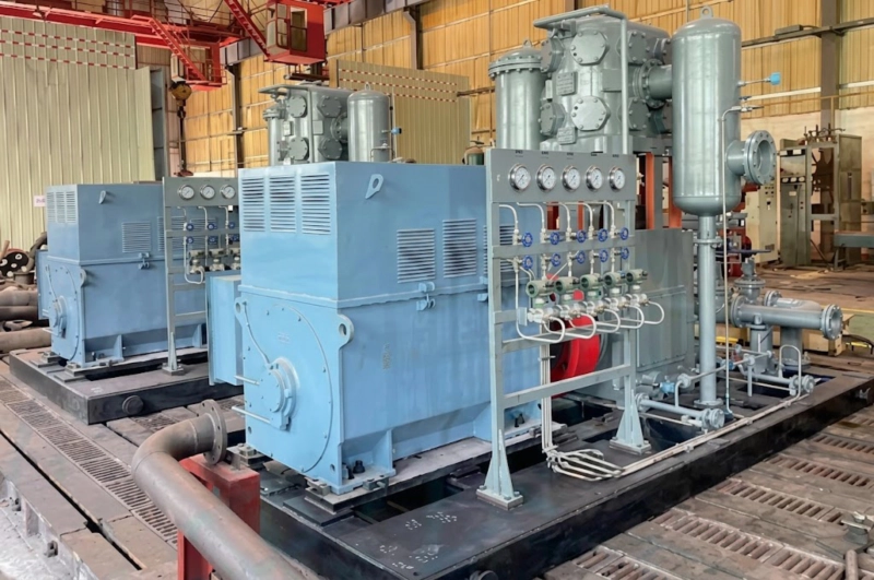
Figure 1: A heavy-duty, 4-Megawatt, symmetrically balanced API-618 compressor. Notice the horizontally opposed cylinder configuration designed specifically to cancel out reciprocating mass forces.
1. The Physics of Destruction: Primary and Secondary Inertial Forces
To engineer a solution, we must first mathematically define the problem. In a reciprocating compressor, the rotational motion of the crankshaft is converted into linear motion by the connecting rod and crosshead. Because the piston must accelerate from a dead stop at Top Dead Center (TDC) to maximum velocity mid-stroke, and then rapidly decelerate to a dead stop at Bottom Dead Center (BDC), massive inertial forces are generated.
The total reciprocating inertial force ($F_{inertia}$) acting along the cylinder axis at any given crank angle ($\theta$) can be precisely modeled by the following kinematic equation:
Where $m$ is the total reciprocating mass, $r$ is the crank radius, $\omega$ is the angular velocity, and $L$ is the length of the connecting rod. This equation reveals two distinct disruptive components:
- Primary Forces ($m r \omega^2 \cos\theta$): These occur once per revolution. On a 4MW machine, accelerating a 500kg piston assembly to 600 RPM generates primary horizontal forces exceeding several tons. If unbalanced, the compressor will violently oscillate back and forth, quickly degrading the epoxy grout and concrete foundation block.
- Secondary Forces ($\frac{m r^2 \omega^2}{L} \cos 2\theta$): These occur twice per revolution, caused by the finite length and angularity of the connecting rod. While smaller in magnitude than primary forces, their higher frequency perfectly aligns with the natural resonant frequencies of high-pressure piping systems, leading to insidious acoustic and structural fatigue.
2. Architectural Supremacy: API-618 Opposed-Balanced Frames
Single-cylinder or “V-type” commercial compressors simply cannot handle the kinetic loads of multi-megawatt process gas compression. To eradicate dynamic vibration, extreme engineering dictates the use of a Symmetrical Horizontally Opposed (Boxer) Architecture.
In this API-618 configuration, cylinders are mounted on opposite sides of a rigid, heavily reinforced cast-iron crankcase. The crankshaft throws for opposing cylinders are set exactly 180° apart. As Piston A travels outward, Piston B travels outward in the exact opposite direction.
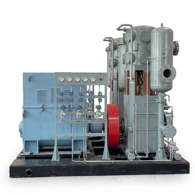
Figure 2: Precision-forged crankshaft and connecting rod assemblies. Notice the immense journal bearings required to handle the residual kinetic forces even in a perfectly balanced system.
However, geometric alignment is not enough. To achieve true kinematic cancellation, the reciprocating mass of opposing throws must be mathematically identical. If Stage 1 is compressing low-pressure gas and requires a massive 800mm diameter piston, and Stage 2 is compressing high-pressure gas requiring only a 300mm piston, the masses are drastically uneven. To solve this, our engineers heavily customize the mass of the crossheads—adding tungsten or high-density steel slugs to the smaller cylinder’s kinematics—so that the total throw weights match within fractions of a gram. The result? The primary horizontal forces equal zero, effectively turning a monstrous 60-ton machine into a dynamically smooth, vibration-free asset.
Engineering Truth: Torsional Vibration (TVA)
“Balancing horizontal forces prevents the compressor from walking off its foundation, but it does not address twisting. On a multi-throw 4MW crankshaft, the alternating compression cycles create severe Torsional Vibration—the shaft literally twists and untwists hundreds of times a minute. We conduct rigorous Torsional Vibration Analysis (TVA) utilizing custom-tuned motor flywheels and specialized elastomeric couplings to shift the resonant frequencies far away from the compressor’s operating speed.”
3. Foundation Dynamics and Grout Degradation
Even with perfect internal mass balancing, a 4MW compressor generates residual dynamic couples (moments) because the opposing cylinders cannot occupy the exact same physical space on the crankshaft; they are offset by the width of a main bearing. This offset creates a slight rotational “yawing” force.
To absorb this residual moment, the structural foundation block must be engineered in tandem with the compressor. The unwritten rule in extreme heavy-duty compression is that the concrete foundation mass must be at least three to five times the mass of the compressor skid. Furthermore, the interface between the cast-iron crankcase and the concrete must utilize highly advanced, non-shrink epoxy grout. If vibration is allowed to degrade this grout line, the structural “soft foot” will exponentially amplify the vibration, leading to rapid main bearing failure and potential crankshaft fracture.
4. Cross-Industry Synergies: Why Medical Plastics Demand Zero Vibration
While the catastrophic risks of 4MW dynamic vibration are most acute in refinery piping and explosive hydrogen loops, the engineering demand for absolute vibration isolation and stable pneumatic delivery is just as strictly enforced in advanced, ultra-clean manufacturing sectors.
Consider the high-speed production of sterile medical IV containers, pharmaceutical vials, or flawless optical-grade PET. These pristine facilities operate relentless, highly calibrated pneumatic machinery that cannot tolerate structural shaking. Driving a modern, precision injection blow molding machine strictly requires up to 40-bar of Class 0, 100% oil-free air, delivered with absolute kinetic stability.

Figure 3: The exact same horizontally opposed kinematic balancing architectures designed to protect refinery foundations are deployed globally to safeguard delicate blow molding machinery from micro-vibration defects.
If a poorly balanced compressor is installed in a medical plastics facility, low-frequency seismic waves propagate through the plant floor directly into the injection molds. This micro-vibration causes microscopic shifts in the core rods during the molten plastic injection phase, resulting in uneven wall thickness and ruining the optical clarity of the medical vial. The entire production batch fails QA. The engineering synergies are striking: whether protecting a high-pressure hydrogen pipeline from fatigue cracking, or protecting a medical vial from optical deformation, mathematically perfect kinematic balancing is the only acceptable mechanical solution.
5. Proving Stability: Dynamic FAT & Laser Verification
Designing a balanced machine on a CAD screen using finite element analysis (FEA) is only the beginning. Validating the harmonic stability of a 4MW compressor requires rigorous, real-world Factory Acceptance Testing (FAT) before the unit ever reaches the client’s site.
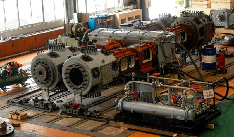
Figure 4: Rigorous FAT verifies the kinematic stability. Multi-axis piezoelectric accelerometers confirm that frame velocity and cylinder vibration remain strictly below API-618 tolerances under full dynamic load.
During full-load FAT, we utilize high-resolution laser interferometry and continuous condition monitoring probes (typically Bently Nevada systems) to measure peak-to-peak vibration velocity across the crankcase, crosshead guides, and cylinder distance pieces. API-618 standard dictates extremely strict limits for overall vibration (often keeping frame velocity below 4.0 mm/s RMS). Only when a compressor demonstrates absolute silence and harmonic stability is it certified for deployment in a volatile petrochemical environment.
6. The EPC Procurement Checklist for Megawatt-Class Dynamics
When EPC contractors and plant reliability engineers specify reciprocating compressors exceeding 1,000 kW, ignoring kinematic analysis leads directly to structural failure and massive plant downtime. We strongly recommend verifying the following dynamic criteria with your vendor:
- ☑
Certified Torsional Vibration Analysis (TVA): Demand an independent TVA report mapping the system’s natural frequencies against the motor speed across all loading steps (0%, 50%, 100%) to guarantee no resonant crossing points. - ☑
Throw-Weight Matching Data: For multi-stage machines, request the actual engineered mass tables for the crossheads and pistons, proving that opposing horizontal kinetic forces mathematically cancel out. - ☑
Active Condition Monitoring: Megawatt-class machines must be factory-fitted with API-670 compliant intrinsically safe vibration monitors (accelerometers and proximity probes) linked directly to the plant’s Emergency Shutdown (ESD) logic solver. - ☑
Comprehensive Unbalanced Force Data: Ensure the vendor provides exact data on residual dynamic moments. Your structural civil engineers need this precise data to calculate the required mass and resonant frequency of the concrete foundation block.
By enforcing strict API-618 horizontally opposed architecture, conducting exhaustive torsional analysis, and integrating continuous vibration monitoring, facility operators entirely neutralize the kinetic threat of 4MW compression. The result is a smooth-running, silent mechanical giant that ensures continuous, high-volume production and ultimate plant safety.
Master the Dynamics of Extreme Compression.
Our elite engineering team specializes in the mathematical modeling, structural casting, and exhaustive FAT validation of multi-megawatt, symmetrically balanced API-618 reciprocating compressors. Designed specifically for massive continuous-duty hydrocracking and syngas processing applications. Do not let unchecked kinetic forces destroy your CAPEX investment.