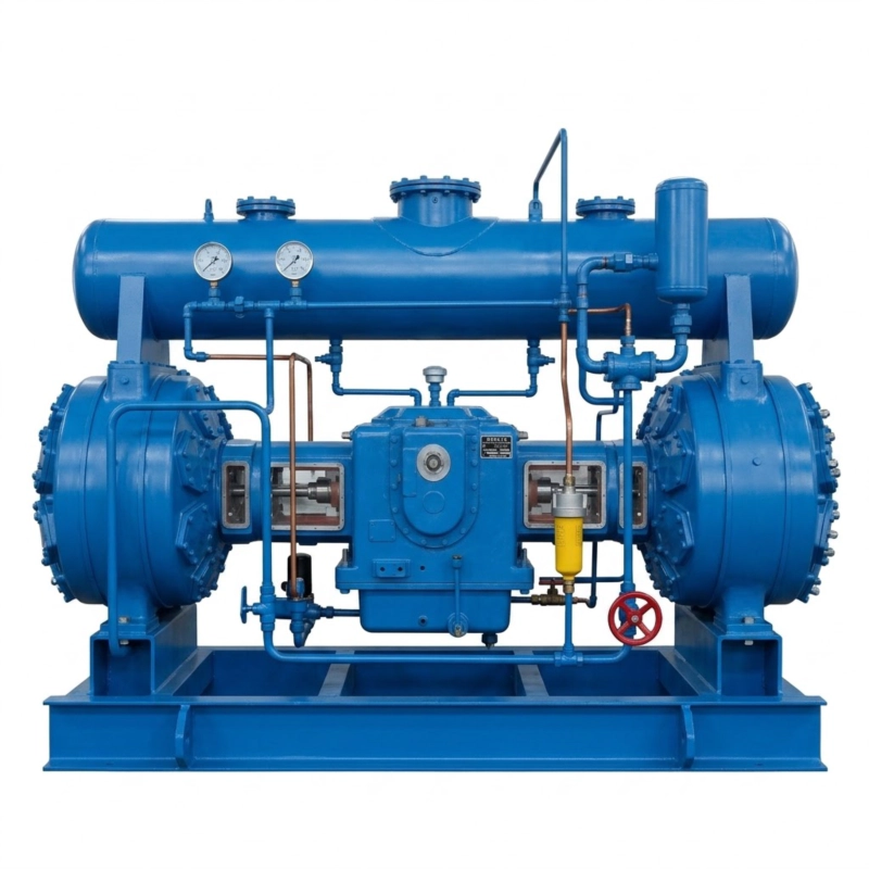
DW-300/1.5 Oil-Free Low-Pressure Air Compressor
Maximize your low-pressure efficiency with the DW-300/1.5 Oil-Free Air Compressor. Deliver 18,000 Nm³/h of ISO Class 0 pure air at 1.5 bar. Get a quote!
1. The Macro-Economics of Mega-Volume Low-Pressure Air (1.5 Bar)
In the highly complex macroeconomic landscape of modern heavy industry, a critical inefficiency has historically plagued manufacturing facilities: the gross misuse of high-pressure utility air for low-pressure applications. Traditional industrial complexes generally operate around a standard 0.7 MPa to 1.0 MPa (7 to 10 bar) centralized pneumatic grid. However, numerous massively energy-intensive processes—such as deep-vat biological fermentation, large-scale pneumatic powder conveying (like PTA, flour, or cement), high-speed textile air-jet looms, and heavy municipal wastewater aeration—strictly require immense volumes of air at significantly lower pressures, typically around 0.15 MPa (1.5 bar).
Historically, many engineering procurement teams attempted to solve this by purchasing standard 7-bar compressors and aggressively throttling or regulating the pressure down to 1.5 bar at the point of use. According to the foundational laws of thermodynamics and fluid mechanics, this approach is mathematically and financially ruinous. Compressing atmospheric air to 7 bar only to immediately expand it back to 1.5 bar wastes staggering amounts of electrical kinetic energy—often resulting in a 40% to 60% loss in total energy efficiency. When processing a colossal volume like 300 cubic meters per minute (18,000 Nm³/h), this artificial pressure-drop inefficiency translates directly into hundreds of thousands of dollars in wasted operational electricity expenditures (OPEX) every single fiscal quarter.
The DW-300/1.5 Oil-Free Low-Pressure Air Compressor represents a radical, purpose-built engineering paradigm shift. By physically designing the machine’s cylinder bore geometries, massive valve flow areas, and stroke lengths specifically for a terminal 1.5-bar discharge, the compressor uses exactly the required electrical power to overcome the low-pressure resistance and not a single kilowatt more. Furthermore, because these low-pressure applications almost universally intersect with deeply sensitive biological, pharmaceutical, or food-grade materials, the DW-300/1.5 guarantees absolute, uncompromising ISO 8573-1 Class 0 oil-free purity. A single microscopic drop of hydrocarbon lubricant aerosolizing into a 1.5-bar pneumatic conveying line could instantly contaminate an entire silo of powdered milk, ruin a pharmaceutical biosynthesis batch, or permanently blind expensive textile weaving equipment. This heavy-duty machine removes the risk of contamination entirely while maximizing massive-scale thermodynamic efficiency.
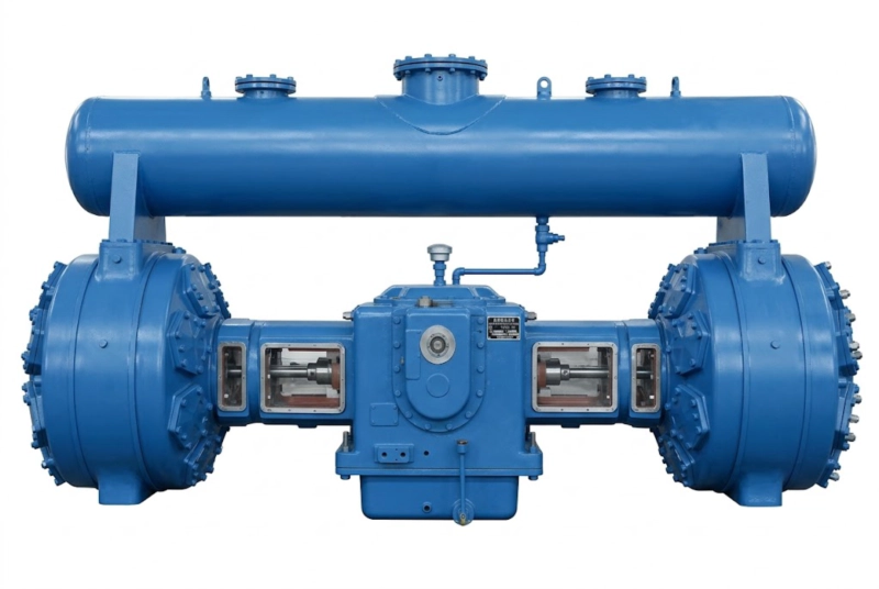
Figure 1: The immense DW-300/1.5 Heavy-Duty Assembly. Purpose-built from the ground up for massive volumetric throughput (18,000 Nm³/h) at a highly efficient, strictly regulated 1.5 bar (0.15 MPa) low-pressure threshold.
2. Exhaustive Technical Specifications & 1.5-Bar Operating Envelope
Managing a staggering 18,000 cubic meters of gas per hour requires structural components of immense physical scale. To achieve 300 Nm³/min without inducing destructive supersonic gas velocities within the machine, the intake manifolds, cylinder bores, and discharge piping must be radically oversized. This specific low-pressure, extreme-volume ratio dictates a highly specialized electrical powertrain, generally commanding a main induction motor ranging from 500 kW to 630 kW. The following comprehensive technical parameters deeply define the uncompromising operational boundaries of the flagship DW-300/1.5 model.
| Technical Parameter | Nominal Value / Engineering Specification |
|---|---|
| Model Designation Architecture | DW-300/1.5 (Mega-Volume Low-Pressure Process Series) |
| Approved Compression Medium | Atmospheric Process Air, High-Volume Nitrogen (N₂) |
| Volumetric Flow Rate (Capacity) | 300.0 Nm³/min (18,000 Nm³/hour) – Continuous Baseload Duty |
| Nominal Suction (Inlet) Pressure | Atmospheric (0.1 MPa absolute) with Mega-Scale Filtration |
| Target Discharge Pressure | 0.15 MPa (1.5 bar / approx. 21.7 psi gauge) |
| Thermodynamic Architecture | Massive Parallel Single-Stage Compression for Ultimate Flow |
| Kinematic Frame & Layout | Heavy-Duty DW-Type (Symmetrical Balanced-Opposed Horizontal) |
| Air Purity Certification | ISO 8573-1 Class 0 (100% Absolutely Oil-Free via physical isolation) |
| Thermal Management Protocol | Heavy-Duty Shell-and-Tube Industrial Water Cooling System |
| Valve Technology Matrix | Oversized Low-Resistance PEEK Polymer Plates (Minimizes ∆P) |
| Main Drive Motor Power | 500 kW to 630 kW (Synchronized via standard Medium-Voltage VFD) |
| Manufacturing Compliance Codes | API-618 (structural dynamics), CE Machinery Directive, ISO 9001 |
Fluid Dynamics Intake Advisory: Pulling 300 cubic meters of air from the atmosphere every sixty seconds acts as a localized vacuum phenomenon. The intake filtration housing must be massive, strategically located outdoors, and shielded from industrial exhaust. If the intake filters become fouled, the pressure drop before the air even enters the cylinders will severely throttle the 18,000 Nm³/h capacity, directly mimicking a highly restrictive high-altitude environment and drastically increasing specific power consumption.
3. The Physics of DW-Type Mega-Volume Parallel Compression
To visually comprehend the mechanical scale of the DW-300/1.5, one must understand the sheer physics of volume. While a high-pressure compressor uses multiple stages of decreasing cylinder sizes to squeeze a small volume into a dense state, this low-pressure machine does the exact opposite. It must forcefully capture and move an incredibly massive physical volume of air. To achieve 18,000 Nm³/h in a reciprocating design, the unit completely abandons sequential multi-staging. Instead, it utilizes a Massive Parallel Single-Stage Architecture. All of the exceptionally large cylinder bores operate simultaneously, drawing in atmospheric air and compressing it directly to 1.5 bar in a single stroke, before converging the massive flow into a singular, colossal discharge header.
Driving multiple, radically oversized pistons horizontally creates an astonishing level of internal mechanical inertia. If these massive cast steel and PTFE pistons were not perfectly harmonized, the resulting kinetic vibration would literally tear the machine from its concrete foundation within hours. This is why the unit is constructed on our elite DW-Type Symmetrical Balanced-Opposed Kinematic Framework.
Figure 2: The sprawling DW-Type architecture. The massive cylinders are arranged perfectly horizontally and directly opposite each other across the heavy-duty forged crankshaft. As one massive piston bank thrusts left, the opposing bank thrusts right, flawlessly mathematically neutralizing the extreme primary and secondary shaking forces.
The foundational crankcase is a masterpiece of metallurgical engineering, cast from ultra-dense nodular iron and internally reinforced to manage half a megawatt of continuous torsional force. By utilizing perfectly weight-matched reciprocating masses acting opposite one another, the destructive inertial forces are internally canceled. The inclusion of heavy-duty, oil-lubricated crosshead mechanisms ensures that the massive lateral thrust generated by the rotating crankshaft is fully absorbed before it reaches the piston rod. This guarantees the long rod travels in a perfectly linear motion, preventing side-loading and ensuring the ultra-large PTFE seals maintain perfect 1.5-bar containment geometry.
4. Uncompromising ISO 8573-1 Class 0 Oil-Free Protection
When 18,000 Nm³/h of air is being injected directly into a 100,000-liter pharmaceutical fermentation bioreactor or used to fluidize and convey thousands of tons of raw baking flour in a pneumatic silo, absolute chemical purity is not a preference—it is a strict legal and biological mandate. Standard rotary screw blowers or lubricated piston compressors utilize liquid oil to seal gaps and cool rotors. This oil inevitably shears into a microscopic aerosol mist. If even a fraction of a part-per-million (PPM) of degraded hydrocarbon oil enters a massive bio-reactor, it will permanently contaminate and destroy millions of dollars of active biological product.
To achieve absolute, uncompromising ISO 8573-1 Class 0 (zero oil) certification, the DW-300/1.5 completely isolates the mechanical lubrication zones from the pneumatic compression zones. The giant compression cylinders operate entirely dry. The massive pistons are equipped with wide, highly proprietary rider bands and compression rings fabricated from virgin Polytetrafluoroethylene (PTFE), heavily matrix-reinforced with aerospace-grade milled glass fiber and high-temperature carbon graphite. This self-lubricating matrix creates a frictionless, hermetic seal against the polished stainless-steel cylinder walls without a single drop of liquid oil.
Because the massive forged crankshaft in the lower housing absolutely requires a pressurized bath of liquid oil to survive the 500+ kW loads, we guarantee separation by deploying engineered API-618 style distance pieces. These are elongated, physical open-air isolation chambers that separate the oily crankcase from the ultra-pure cylinders. Heavy-duty scraper rings wipe the piston rod entirely dry as it travels through this gap, ensuring that it is physically and mechanically impossible for liquid oil to creep up the rod and contaminate your colossal low-pressure air supply.
5. Low-Pressure Thermodynamics and High-Volume Valve Dynamics
While 1.5 bar (0.15 MPa) is technically “low pressure,” compressing 300 cubic meters of air every single minute still subjects the gas to the unyielding laws of adiabatic thermodynamics. The act of forcing that massive volume into a slightly smaller space generates kinetic friction and heat. If left unmanaged, the continuous discharge temperature would comfortably exceed 130°C. Injecting 130°C air into a sensitive biological fermentation tank or a PVC powder pneumatic conveying line would cause immediate thermal degradation of the product and potentially trigger powder melting and catastrophic pipe blockages.
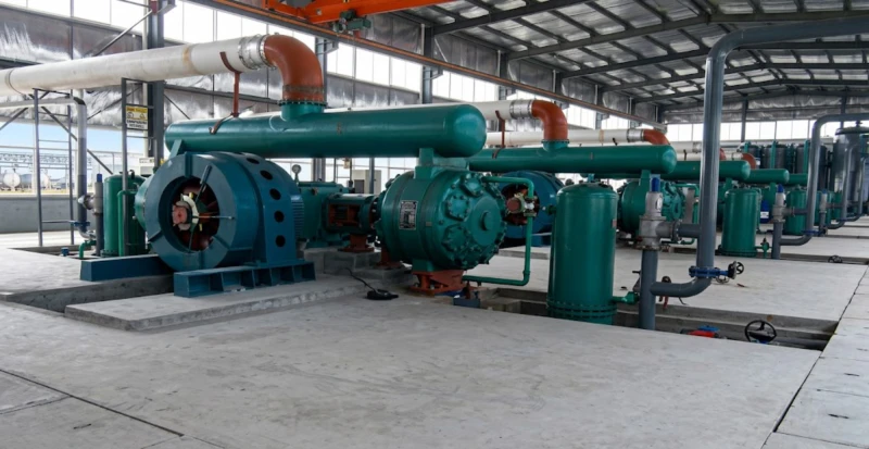
Figure 3: Detailed view of the massive discharge shell-and-tube water cooling architecture. Before the 18,000 Nm³/h of air is released into your facility’s pneumatic grid, it is forcefully routed through this heavy-wall heat exchanger, rapidly stripping the adiabatic heat away using cold industrial water.
To completely neutralize this thermal threat, the DW-300/1.5 features heavily integrated, oversized shell-and-tube water coolers on the final massive discharge manifold. By forcing the hot 1.5-bar air through a dense internal network of stainless steel tubes surrounded by a continuous high-volume flow of chilled facility water, the discharge temperature is aggressively dropped to just a few degrees above the ambient cooling water temperature. This ensures your downstream biological and chemical processes receive massive volumes of dense, perfectly cool air.
Equally critical are the internal gas valves. In a machine pushing 18,000 Nm³/h, even a microscopic restriction in the intake or discharge valves will create a severe pressure drop (∆P). If the machine has to push extra hard just to get the air past its own internal valves, it wastes tens of thousands of dollars in electricity. We deploy radically oversized, highly optimized valve assemblies featuring ultra-durable, lightweight PEEK (Polyether ether ketone) aerospace polymer plates. These PEEK plates open instantaneously with minimal aerodynamic resistance, providing a massive flow area that mathematically guarantees near-perfect volumetric efficiency and vastly reduces the total kilowatts required per cubic meter of air.
6. Crushing the OPEX: VFD Integration and Total Cost of Ownership (TCO)
When operating a heavy industrial machine utilizing a massive 500 kW to 630 kW main induction motor, the initial capital expenditure (CAPEX) of purchasing the machine is rapidly eclipsed by the staggering operational electricity expenditure (OPEX) over a 20-year lifecycle. In massive aeration or conveying systems, real-time demand fluctuates. Running a half-megawatt motor at a rigid, fixed 100% speed 24/7/365, only to mechanically bypass or vent excess 1.5-bar air when demand drops, is an egregious financial hemorrhage.
Massive VFD Electrical Savings
The DW-300/1.5 is explicitly engineered for seamless integration with high-voltage Variable Frequency Drives (VFD). By utilizing highly advanced algorithms, the central PLC dynamically manipulates the electrical sine wave frequency supplied to the massive motor. If the plant’s fermentation tanks only require 12,000 Nm³/h instead of the full 18,000 Nm³/h, the VFD instantaneously slows the rotational RPM of the massive crankshaft. Because electrical power consumption drops exponentially with speed reduction, this precise real-time synchronization can easily yield over $150,000 USD in pure electrical savings annually, achieving a massive Return on Investment (ROI).
Unmatched Mechanical Longevity
Because the DW-300/1.5 achieves its massive 1.5-bar volume through enormous physical cylinder displacement rather than extremely high, friction-inducing rotational speeds (as seen in high-speed turbo blowers), the internal mechanical wear is drastically minimized. The heavy-duty cast iron frame, forged crankshaft, and aerospace-grade PTFE sealing matrix operate at a highly conservative, rhythmic pace. This dramatically extends the Mean Time Between Failures (MTBF), ensuring that the machine will continuously drive your facility’s baseload operations for 20 to 25 years with only highly predictable, scheduled consumable maintenance.
7. Strategic Industrial Synergies: Clean Conveying to Final Packaging
In massive petrochemical and advanced polymer manufacturing complexes, the generation of 18,000 Nm³/h of ultra-pure 1.5-bar air is frequently deployed for the massive pneumatic conveying of raw polymer chips (such as PET, PE, or PP pellets). Moving thousands of tons of raw plastic pellets from reaction silos directly to the final injection and molding halls requires an uninterrupted, highly powerful, entirely oil-free pneumatic flow to prevent product contamination and pipeline blockages.
To fully empower our global EPC clients with true end-to-end vertical integration, we provide deeply complementary downstream polymer processing equipment. Once our mega-volume DW-300/1.5 compressors successfully convey your pure polymer pellets to the manufacturing floor, we strongly recommend integrating our advanced Blow Molding Machine technology. This highly sophisticated injection stretch blow molding system takes the pure, uncontaminated raw polymer and rapidly processes it into flawless, absolutely leak-proof, highly sterile rigid containers and medical bottles. Utilizing this integrated machinery ecosystem ensures that your high-value resins are safely conveyed and perfectly packaged with zero risk of catastrophic oil contamination from start to finish.
8. Extreme Industry 4.0 Automation and Complete SCADA Connectivity
Governing a colossal pneumatic asset that processes 300 cubic meters of gas every minute requires decision-making speeds and monitoring capabilities far beyond human operators. To completely mathematically mitigate all dynamic operational risks, the DW-300/1.5 is strictly governed by a state-of-the-art, heavily fortified Industry 4.0 digital automation architecture. The central digital brain is an ultra-high-speed programmable logic controller (PLC), typically deploying the premium Siemens S7-1500 or Allen-Bradley ControlLogix platforms, renowned globally for absolute zero-latency reliability in severe heavy industrial environments.
This premium PLC is continuously fed massive amounts of live, micro-second data from an incredibly dense array of specialized field sensors. High-precision RTDs monitor extreme gas temperatures at every intake and massive discharge manifold. Because of the enormous physical reciprocating mass, highly sensitive kinetic vibration monitors (deploying proximity probes directly on the main crankcase) strictly ensure the heavy machine operates flawlessly within its harmonic envelope.
If critical parameters rapidly breach physical limits—such as a sudden massive spike in 1.5-bar discharge pressure indicating a severe downstream conveying pipe blockage, or a critical loss of cooling water flow—the PLC instantaneously triggers a multi-tiered fail-safe protocol. It will immediately sever the massive main half-megawatt power supply, aggressively open pneumatically-piloted relief valves to safely vent the massive volume of trapped air, and isolate the machine to neutralize the hazard. Furthermore, utilizing highly robust industrial communication protocols (Modbus TCP/IP, Profinet) via heavily shielded fiber-optic networks, the massive compressor skid seamlessly integrates directly into the mega-plant’s Distributed Control System (DCS), granting the central control room full live visibility and total remote start/stop command capabilities.
9. Massive Civil Engineering Requirements & EPC Logistics
Executing a successful procurement and deployment strategy for a colossal 18,000 Nm³/h heavy industrial compressor is not merely a matter of equipment delivery; it fundamentally requires highly strict, heavy-duty site civil engineering preparation. Dealing with an immense, multi-ton reciprocating mechanical system driven by a half-megawatt motor necessitates a structural engineering focus almost entirely dedicated to managing immense dynamic loads and preventing low-frequency destructive kinetic vibration from transferring into your facility’s surrounding architecture.
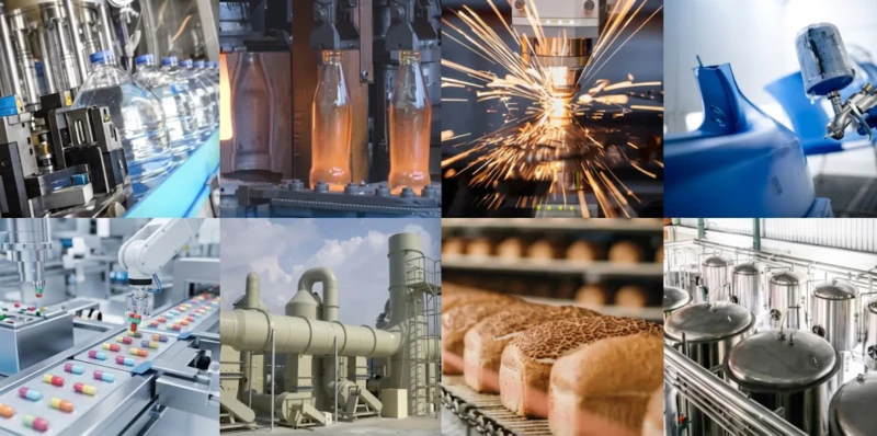
Figure 4: Strategic deployment of massive-volume pneumatic infrastructure. The scale of the DW-300/1.5 dictates that proper heavy civil engineering and a deep, isolated concrete foundation block are strictly mandated to safely operate this machinery across a 25-year lifecycle.
While the DW-Type symmetrical balanced-opposed geometry brilliantly cancels out primary shaking forces, the massive overall static weight of the enormous skid strictly requires a deeply excavated, highly dedicated, vibrationally isolated reinforced concrete foundation block. Our senior fluid dynamics and civil engineering teams provide exhaustive, dimensionally accurate 3D CAD foundation blueprints directly to your EPC firm months before delivery. This heavy concrete block must be poured precisely, utilizing deep-set, ultra-heavy-duty J-style steel anchor bolts and high-strength industrial epoxy grout. The physical mass of this concrete block is calculated to be typically 5 to 7 times the total static weight of the compressor skid to mathematically absorb and nullify any residual harmonic vibrations.
10. Executive Technical FAQ: DW-300/1.5 Mega-Volume Operations
To support rapid, deep engineering evaluation by global EPC firms, heavy manufacturing planners, and municipal wastewater engineers, our senior technical team has exhaustively distilled the ten most critical inquiries regarding the deployment of the massive 18,000 Nm³/h DW-300/1.5 low-pressure compressor.
1. Why should we purchase a dedicated 1.5-bar compressor instead of regulating our 7-bar system down?
2. What are the primary applications for 18,000 Nm³/h of 1.5-bar air?
3. How does the machine guarantee ISO Class 0 “100% Oil-Free” purity?
4. Is a 300 Nm³/min reciprocating compressor inherently prone to severe vibration?
5. Does this machine utilize multi-stage compression?
6. Why are PEEK polymer valves used instead of standard stainless steel?
7. Can the compressor be integrated directly into our massive DCS network?
8. What happens if our pneumatic conveying line suddenly blocks?
9. Is water cooling strictly necessary for a low-pressure machine?
10. How heavily must the foundation be engineered for installation?
Command Massive Pneumatic Flow with Absolute Efficiency
Stop hemorrhaging OPEX by wastefully regulating high-pressure utility grids. Radically transform the efficiency of your massive pharmaceutical fermentation networks, municipal wastewater aeration basins, and bulk pneumatic powder conveying systems. Deploy the unrelenting 18,000 Nm³/h capacity of the DW-300/1.5 to secure mathematically perfect 1.5-bar precision, uncompromising ISO Class 0 oil-free purity, and disruptive factory-direct B2B heavy equipment pricing today.
Request a Factory-Direct Technical Quote
Our highly dedicated, deeply experienced senior pneumatic fluid dynamics engineering team will rigorously review your exact massive 1.5-bar flow requirements, ambient site elevation metrics, and complex civil engineering constraints. Expect a mathematically verified severe-duty sizing prospectus, complete heavy 3D CAD deep foundation schematics, and highly transparent global EPC procurement pricing strictly within 24 hours.