
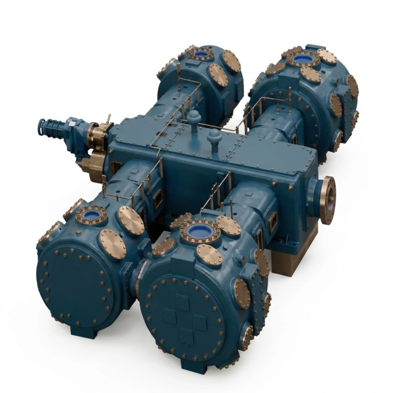
4MW-100/100 Oil-Free High-Pressure Air Compressor
Discover the 4MW-100/100 Oil-Free High-Pressure Air Compressor. Delivers 6000 Nm³/h of ISO Class 0 pure air at 100 bar. Megawatt 4-stage heavy industry system.
1. The Macro-Economics and Physics of 100-Bar Mega-Volume Oil-Free Air
Within the most elite, highly specialized echelons of the global macroeconomic landscape, the generation of 10.0 MPa (100 bar) compressed air at a massive continuous volume of 6000 Nm³/h transcends standard industrial utility—it enters the realm of extreme fluid dynamics and heavy infrastructural kinetic power. To contextualize this scale, a standard industrial manufacturing facility operates its entire automated pneumatic grid at a mere 7 bar. Even the global heavy PET beverage packaging sector maxes out its primary high-pressure blow molding operations at 40 bar. Pushing 100 cubic meters of atmospheric air every single minute into a 100-bar state requires compressing the gas to one one-hundredth of its original physical volume, generating an apocalyptic level of internal molecular resistance, kinetic heat, and dynamic rod load.
The industrial applications that demand this terrifying level of pneumatic force are deeply integrated into national infrastructure, defense, and advanced mega-manufacturing. Aerospace engineering firms utilize 100-bar, massive-volume air to forcefully drive supersonic and hypersonic aerodynamic wind tunnels, simulating extreme Mach velocities over experimental aircraft fuselages. Massive heavy metallurgical facilities utilize 100-bar air for explosive descale operations on raw glowing steel billets. Advanced petrochemical complexes rely on continuous 100-bar air for critical deep-tank chemical oxidation processes, where the immense hydrostatic head pressure of a 50-meter-tall chemical reactor must be aggressively overcome. Furthermore, specialized heavy marine and naval engineering sectors deploy this air for massive ballast blowing and deep-sea acoustic seismic testing arrays.
However, achieving 100 bar with standard lubricated compression technology presents an absolute, mathematically guaranteed catastrophic hazard. At 100 bar, the partial pressure of oxygen within the compressed air is multiplied by a factor of 100. In terms of chemical reactivity, 100-bar atmospheric air behaves almost identically to pure, highly reactive liquid oxygen. If a standard oil-injected compressor attempts to reach these pressures, the vaporized hydrocarbon lubricating oil aggressively mixes with the hyper-dense oxygen. When subjected to the violent adiabatic heat of compression, this mixture instantly achieves auto-ignition via the “diesel effect.” This causes a localized, uncontrollable metal fire and subsequent detonation within the heavy steel pipelines, capable of leveling an entire industrial block. The 4MW-100/100 completely mathematically eliminates this fatal risk. It operates with a strictly 100% dry-running, multi-stage architecture, physically isolating all crankcase lubrication behind heavy API-618 distance pieces, guaranteeing ISO 8573-1 Class 0 absolute purity and securing an impregnable, explosion-proof pneumatic baseload for your mega-facility.
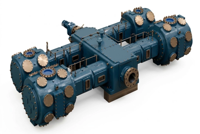
Figure 1: The Apex 4MW-100/100 Heavy-Duty 4-Stage Assembly. A true megawatt-class industrial titan engineered specifically to relentlessly draw massive volumes of atmospheric air and aggressively compress it to an uncompromising 100-bar (10.0 MPa), 100% oil-free state.
2. Exhaustive Technical Specifications & 100-Bar Megawatt Operating Envelope
Precision fluid dynamics scaled to a 100-bar (10.0 MPa) terminal pressure at a colossal 6000 Nm³/h volume mandates that every single internal structural component, heavy forging, and electrical powertrain element is mathematically mapped to withstand extreme, continuous multi-megawatt punishment. Forcing 100 cubic meters of air per minute through a staggering 100:1 total compression ratio generates immense, unyielding kinetic resistance. To overcome this, the machine requires a highly robust, massive high-voltage electrical drive system, strictly necessitating a main induction or synchronous motor rating typically ranging from 1,200 kW to 1,600 kW (1.2 to 1.6 Megawatts). The following highly comprehensive technical parameters strictly define the extreme operational boundaries of the flagship 4MW-100/100 model.
| Technical Parameter | Nominal Value / Engineering Specification |
|---|---|
| Model Designation Architecture | 4MW-100/100 (4-Stage Extreme High-Pressure Megawatt Series) |
| Approved Compression Medium | Atmospheric Process Air, High-Purity Nitrogen (N&sub2;), Argon (Ar) |
| Volumetric Flow Rate (Capacity) | 100.0 Nm³/min (6000 Nm³/hour) – Continuous Baseload Duty |
| Nominal Suction (Inlet) Pressure | Atmospheric (0.1 MPa absolute) via Mega-Scale Intake Silencer/Filter |
| Target Discharge Pressure | 10.0 MPa (100.0 bar / approx. 1,450 psi) |
| Thermodynamic Architecture | Strict 4-Stage Sequential Compression with Deep Intercooling |
| Kinematic Frame & Layout | Heavy-Duty MW-Type (Symmetrical Balanced-Opposed Horizontal) |
| Air Purity Certification | ISO 8573-1 Class 0 (100% Absolutely Oil-Free via physical separation) |
| Thermal Management Protocol | Massive Heavy-Wall Shell-and-Tube Industrial Water Cooling System |
| High-Pressure Sealing Material | Proprietary Extreme-Pressure Glass/Bronze Reinforced PTFE Matrix |
| Main Drive Motor Power | 1,200 kW to 1,600 kW (High-Voltage 6kV/10kV Synchronous or Induction) |
| Manufacturing Compliance Codes | API-618, CE Machinery Directive, ASME Section VIII Div 2, ISO 9001 |
High-Voltage EPC Integration Advisory: A megawatt-class motor cannot be simply plugged into a standard factory grid. The 1.2 to 1.6 MW main drive strictly requires a dedicated medium-to-high voltage electrical substation (typically 6,000V or 10,000V architecture). Direct-On-Line (DOL) starting is strictly prohibited as the massive inrush current would severely destabilize the local municipal power grid. EPC contractors must procure and integrate a high-voltage Soft Starter or a massive high-voltage Variable Frequency Drive (VFD) to safely ramp up the rotational inertia of the multi-ton forged crankshaft.
3. The Extreme Thermodynamics of 4-Stage 100-Bar Compression
Attempting to compress atmospheric gas from a foundational state of 1.0 bar absolute directly to a terminal state of 100 bar represents a completely mind-bending 100:1 volumetric reduction. According to the foundational laws of adiabatic thermodynamics (specifically mathematically modeled by the equation T2 = T1 × (P2/P1)(k-1)/k), mechanically forcing a gas into such a hyper-dense state results in an exponentially violent spike in kinetic molecular heat. If an engineering team attempted to bridge this immense pressure ratio in only one or two mechanical stages, the instantaneous discharge temperatures would effortlessly exceed 800°C. In this extreme thermal environment, the internal self-lubricating PTFE friction seals would instantly vaporize into toxic hydrofluoric gas, the massive forged steel valves would literally melt and fuse to the cylinder heads, and the volumetric efficiency would utterly collapse as the superheated, aggressively expanding gas mathematically refuses further compression.
To mathematically enforce a strict, unbreakable thermal safety boundary, the 4MW-100/100 meticulously and intelligently divides the total multi-megawatt mechanical workload across four entirely distinct, mathematically balanced sequential compression stages. By stepping the pressure up gradually through a precisely calculated thermodynamic cascade, the total 100:1 pressure ratio is reduced to a highly manageable ∼3.16:1 ratio per stage (3.16 × 3.16 × 3.16 × 3.16 ≈ 100).
- Stage 1 (Mass Intake & Densification): Twin massive low-pressure cylinders rapidly draw 6000 Nm³/h from the atmosphere, aggressively compressing it to approximately 3.2 bar, immediately prepping the mass density for the high-pressure circuits.
- Stage 2 (Intermediate Heavy Boost): The heavily cooled air is drawn from the first intercooler and compressed further to roughly 10.0 bar, forcing the oxygen matrix closer together.
- Stage 3 (High-Pressure Transition): The gas enters the smaller, radically heavy-walled forged steel cylinder, aggressively boosting the pressure to an intense 32.0 bar.
- Stage 4 (Terminal Extreme 100-Bar Discharge): The final, highly reinforced smallest cylinder—machined from a solid billet of aerospace alloy steel—forcefully drives the highly dense gas into the critical 100.0 bar industrial target.
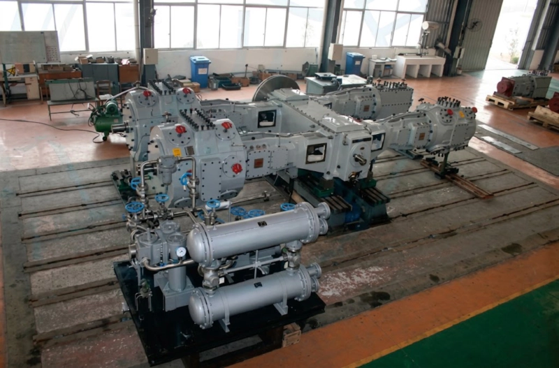
Figure 2: The 4-Stage Thermodynamic Cascade & Extreme Intercooling. Notice the sprawling network of heavy-wall high-pressure steel pipelines routing the air between the progressively smaller cylinders. These pipes lead directly into massive shell-and-tube water coolers designed to strip the violent adiabatic heat away after every single compression stroke.
The absolute secret to this massive system’s immense efficiency and extreme heavy-duty longevity is its sprawling inter-stage shell-and-tube thermal management architecture. Between every single compression cylinder stroke, the aggressively heated process air is violently routed through massive, extreme-pressure heavy-wall heat exchangers constructed to strictly comply with ASME Section VIII Div 2 standards. These enormous units require a continuous, highly pressurized flow of thousands of liters of chilled, chemically softened industrial facility water per minute. As the hot 100-bar-bound air passes through the internal high-alloy tube bundle, the cold water rapidly strips away the intense kinetic heat. This deep thermal cascading mathematically guarantees that the air entering the subsequent compression stage is highly dense and cooled to below 45°C. This process drastically reduces the total electrical megawatts required by the colossal main motor and guarantees the final 100-bar discharge temperature never exceeds the strict mechanical limit of 150°C.
4. Extreme Material Science: Surviving 100-Bar Oil-Free Environments
Achieving 100-bar continuous extreme pressure without utilizing liquid oil for internal cylinder sealing is widely considered one of the most profound metallurgical and chemical engineering challenges in modern heavy machinery. Standard oil-flooded compressors simply pump gallons of heavy synthetic oil into the cylinders to seal the massive pressure gaps and absorb the explosive heat. But at 100 bar, as previously detailed, injecting oil into what is functionally a hyper-dense oxygen environment invites total catastrophic explosive failure. Furthermore, downstream applications such as blowing highly sensitive pharmaceutical-grade polymers or purging hyper-sensitive semiconductor cleanrooms cannot tolerate even a microscopic fraction of a part-per-billion (PPB) of hydrocarbon aerosol.
To confidently secure the highly coveted, absolute ISO 8573-1 Class 0 (zero oil) purity certification, the 4MW-100/100 completely abandons liquid lubrication within the extreme-pressure gas path. The massive pistons utilize highly proprietary, extremely thick piston rings, immense load-bearing rider bands, and heavily reinforced primary rod packing sets fabricated from virgin Polytetrafluoroethylene (PTFE). Because pure PTFE would rapidly physically extrude, deform, and melt under the apocalyptic 100 bar of pressure and friction, our advanced polymer matrix is aggressively and heavily alloyed with aerospace-grade milled glass fibers, high-temperature carbon graphite, and specialized structural bronze powder. This creates an incredibly dense, rigid, self-lubricating dynamic labyrinth seal. As the heavy piston oscillates violently, a microscopic layer of the advanced PTFE blend permanently bonds to the highly polished, specially hardened stainless steel cylinder walls, creating a flawless, frictionless hermetic seal that traps the 100-bar air without any liquid assistance whatsoever.
However, the massive multi-ton forged alloy crankshaft and giant crosshead bearings located in the lower crankcase strictly require a highly pressurized, continuous flood of liquid hydrocarbon oil to survive the colossal 1.5-Megawatt mechanical loads and prevent the metal from instantly seizing. To mathematically and physically guarantee this oil never migrates into the pure air stream, the machine is constructed utilizing deeply extended, heavily ventilated API-618 Type-C Double Compartment Distance Pieces. These act as open-air physical isolation structural chambers, vastly separating the oily crankcase from the ultra-dry compression cylinders. Specialized heavy-duty scraper rings wipe the massive piston rod entirely dry as it leaves the lower casing. Because of this massive physical open-air gap, it is physically, mechanically, and mathematically impossible for crankcase oil to travel upward and breach the 100-bar clean air zone.
5. Managing Megawatt Loads: The Physics of MW-Type Kinematic Balancing
Mechanically capturing massive volumes of gas and violently forcing it through a 4-stage cascade up to an unforgiving 100 bar generates staggering dynamic rod loads that border on the limits of terrestrial mechanical engineering. When the final 4th-stage high-pressure piston aggressively pushes against an unyielding 100-bar wall of highly dense pneumatic resistance—driven by the sheer, terrifying torque of a 1.5-Megawatt motor—the resulting kinetic shockwave translating down the thick connecting rod to strike the crankshaft is immense. If the heavy cylinders were arranged vertically or in a standard V-shape, these violently alternating kinetic forces would induce catastrophic, low-frequency dynamic vibrations capable of rapidly fatiguing the main compressor frame, violently shattering the connected high-pressure pipeline infrastructure, and literally fracturing the concrete factory floor.
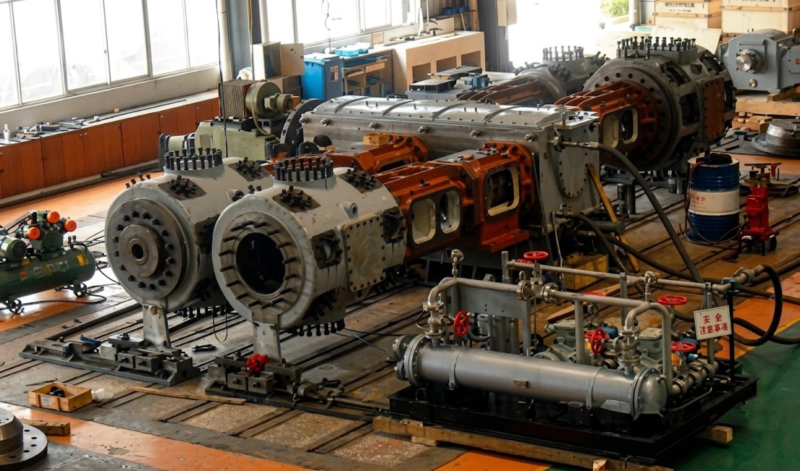
Figure 3: Rigorous Factory Acceptance Testing (FAT). The massive MW-Type architecture is placed under extreme load. The four compression cylinders are arranged strictly horizontally across the heavy-duty forged crankshaft, geometrically neutralizing the destructive low-frequency vibration generated by the 100-bar dynamic rod loads.
To completely conquer and domesticate these extreme internal kinetic forces, the 4MW-100/100 is forged upon a sprawling, hyper-rigid MW-Type Symmetrical Balanced-Opposed Kinematic Architecture. The foundational crankcase is an absolute masterpiece of modern metallurgy, cast from ultra-dense, stress-relieved nodular iron. The four massive compression cylinders are arranged strictly horizontally, extending outward from the central crankcase. Stage 1 is positioned exactly opposite Stage 2, and Stage 3 is exactly opposite Stage 4.
Because the reciprocating masses (the heavy steel pistons, the massive cast crossheads, and the thick connecting rods) are precisely weight-matched down to the specific gram by our senior engineers, their high-speed reciprocating movements perfectly counteract one another. When the Stage 3 piston thrusts aggressively outward to compress gas, the heavily opposing Stage 4 piston simultaneously thrusts in the exact opposite direction. This brilliant geometric symmetry mathematically cancels out the highly destructive primary and secondary shaking inertial forces. The final result is a colossal megawatt-class machine that operates with uncanny, astonishing smoothness, fiercely protecting the structural integrity of your massive 100-bar high-pressure piping network.
6. Strategic Industrial Synergies: From Extreme Pressure to Polymer Packaging
As a highly comprehensive global industrial engineering provider, we deeply understand that generating 6000 Nm³/h of 100% oil-free, 100-bar process air is almost exclusively the foundational heavy utility phase for a much larger, highly profitable and complex manufacturing ecosystem. Beyond aerospace testing and metallurgical descale, one of the most financially critical applications globally is acting as the central high-pressure utility hub for massive, multi-line advanced polymer packaging complexes. By generating 100 bar centrally, massive factories can easily step the pressure down to perfectly regulated 40-bar and 22-bar highly stable local loops for different manufacturing halls.
To actively support our major global EPC clients’ complete end-to-end vertical integration strategies, we proudly design and manufacture deeply complementary, ultra-high-precision downstream polymer processing equipment. For massive beverage, pharmaceutical, or chemical packaging facilities utilizing our centralized extreme-pressure oil-free compressor networks, we strictly recommend seamlessly integrating our advanced Blow Molding Machine technology directly into your final automated packaging halls. This state-of-the-art injection stretch blow molding system relies exclusively on the pristine, completely uncontaminated process air generated by machines like the 4MW-100/100. When the high-pressure air is violently injected into the heated thick-walled polymer preform, it flawlessly expands the dense plastic into the intricate mold cavity in milliseconds, producing absolutely perfect, highly rigid, extreme-barrier consumer bottles. Utilizing this advanced packaging machinery in tandem guarantees that your high-value consumer products are hermetically packaged with zero risk of catastrophic oil contamination.
7. Extreme Valve Material Science: Mastering 100-Bar Fatigue
The extreme 100-bar high-pressure gas valves located in the 3rd and 4th compression stages act as the literal mechanical beating heart of the machine. These valves must aggressively snap open and violently slam shut millions of times a month against an unrelenting, hyper-dense 100-bar wall of hot air. Traditional commercial stainless steel valve plates suffer from rapid, severe high-cycle impact fatigue in these apocalyptic environments. Within mere weeks, standard metallic valves will fatigue, crack, violently shatter, and ingest hardened metal fragments directly into the high-pressure cylinders, causing immediate, catastrophic internal destruction and massive production downtime.
To permanently engineer this critical failure point out of existence, the 4MW-100/100 exclusively employs massively oversized, highly complex valve plates precision-machined from raw, solid PEEK (Polyether ether ketone) for the intermediate stages, and specialized custom aerospace-grade titanium steel alloys for the terminal 100-bar stage. PEEK is an incredibly advanced aerospace thermoplastic that offers genuinely unmatched flexural impact strength and ultra-low mass, allowing the valves to open and close instantaneously to minimize aerodynamic pressure drop (∆P). For the ultimate 100-bar discharge valves, our bespoke titanium-alloy plates possess the extreme tensile strength required to withstand the 100-bar slam without ever suffering from fatigue fragmentation. This highly advanced material science integration extends the Mean Time Between Failures (MTBF) for valve components by over 400% compared to standard alternatives, keeping your megawatt facility running continuously.
8. Extreme Industry 4.0 Automation, SCADA, & SIL-Rated Fail-Safe Security
Relying entirely on traditional manual human operator oversight for a highly complex 4-stage machine consuming 1.5 Megawatts of electricity and generating 100-bar extreme pressure is not just inefficient—it is totally unacceptable and highly dangerous in the modern digital industrial era. To absolutely, scientifically mitigate all dynamic operational risks, the colossal 4MW-100/100 is rigorously governed by a state-of-the-art, heavily fortified, SIL-rated (Safety Integrity Level) Industry 4.0 digital automation architecture. The central digital brain is a premium, ultra-high-speed programmable logic controller (PLC), typically deploying the advanced Siemens S7-1500 or Allen-Bradley ControlLogix series, widely renowned globally for absolute zero-latency reliability in severe heavy industrial environments.
This premium central PLC is continuously fed live, micro-second data from an incredibly dense array of specialized industrial field sensors. High-precision RTDs actively monitor critical gas and cooling water temperatures at every single massive intake, inter-stage heavy-wall cooler, and the extreme 100-bar discharge point simultaneously. Extreme high-pressure transmitters strictly monitor stage ratios. Because of the massive reciprocating weight, highly sensitive kinetic vibration monitors (utilizing advanced Bently Nevada-style proximity probes installed directly on the main crankcase and crosshead guides) strictly ensure the heavy machine operates flawlessly within its harmonic envelope.
If critical parameters rapidly breach physical limits (e.g., a massive loss of cooling water flow, or a 105-bar overpressure event indicating a highly dangerous downstream pipe blockage), the PLC instantaneously triggers an automated fail-safe protocol. It severs the massive 1.5 MW main power, aggressively activates pneumatically-piloted 100-bar safety blowdown valves to safely and rapidly vent all trapped extreme-pressure gas to a safe atmospheric silencer, and mechanically isolates the machine to neutralize any hazard. Utilizing robust industrial communication protocols like Modbus TCP/IP or Profinet via heavily shielded fiber-optic networks, the massive compressor skid seamlessly integrates into your mega-plant’s primary Distributed Control System (DCS) for complete remote operation and live data trending.
9. Massive Civil Engineering Requirements & Global EPC Logistics
Executing a highly successful, profitable EPC procurement strategy for a colossal 100-bar, 1.5-megawatt heavy industrial compressor is a monumentally complex task that fundamentally requires highly strict, heavy-duty site civil engineering physical preparation. When dealing with an immense reciprocating multi-ton steel kinetic mass violently pushing against an unrelenting 100-bar wall of highly dense aerodynamic resistance, the structural engineering focus shifts entirely to safely managing immense dynamic rod loads and preventing low-frequency destructive kinetic vibration from violently transferring into your facility’s surrounding architecture.
Figure 4: Strategic deployment of massive megawatt-class high-pressure pneumatic infrastructure. Proper heavy civil engineering and a massively deep, highly isolated reinforced concrete foundation block are strictly mandated to safely anchor and operate this 100-bar machinery over a grueling 25-year operational lifecycle.
Proper, vigorously mathematically validated heavy civil engineering structural foundation preparation is absolutely, strictly critical. The immense overall static and dynamic weight of the colossal 4-stage skid (often exceeding 50 metric tons) strictly requires a deeply excavated, highly dedicated, vibrationally isolated reinforced concrete foundation block. During the initial technical procurement phase, our senior civil engineering team provides exhaustive, dimensionally accurate 3D civil foundation CAD blueprints directly to your local EPC contractors. This heavy concrete mass is typically calculated to be 5 to 7 times the total static weight of the entire compressor skid (frequently equating to 250 to 350 tons of poured concrete), utilizing deep-set, ultra-heavy-duty J-style anchor bolts and specialized high-strength industrial epoxy grout. This massive concrete inertia block perfectly absorbs and mathematically nullifies any residual kinetic vibrations.
10. Executive Technical FAQ: 4MW-100/100 Megawatt High-Pressure Operations
To effectively support rapid, deep engineering evaluation by massive global EPC firms, highly advanced aerospace facility designers, and extreme-pressure petrochemical planners, our senior technical team has exhaustively distilled the ten most critical technical inquiries regarding the deployment of the colossal 100-bar 4MW-100/100 compressor.
1. What industrial applications genuinely require 6000 Nm³/h of air at 100 bar?
2. How is ISO 8573-1 Class 0 “100% Oil-Free” purity mechanically guaranteed at 100 bar?
3. Why does compressing to 100 bar require a massive 4-stage architecture?
4. What specific materials survive the impact of 100-bar high-speed valve operation?
5. How do we power a 1.5 Megawatt motor without collapsing the local factory grid?
6. What are the heavy foundation civil engineering requirements for this colossal machine?
7. Can the massive 100-bar compressor seamlessly integrate with our central DCS system?
8. What exact type of cooling water system is strictly required to operate this machine?
9. How long do the PTFE dry-running piston rings survive under 100-bar extreme stress?
10. What safety protocols trigger if a downstream 100-bar pipe is dangerously blocked?
Command Megawatt Extreme-Pressure Performance
Master the absolute limits of highly demanding, deeply critical 100-bar extreme-pressure pneumatic requirements for global aerospace testing, deep geological storage, and massive central utility hubs. Forcefully power your mega-scale operations with the unrelenting 6000 Nm³/h capacity of the 4MW-100/100. Secure world-class ISO 8573-1 Class 0 absolute oil-free air, unbeatable 4-stage MW-Type endurance, and highly transparent factory-direct B2B heavy equipment procurement today.
Request a Factory-Direct Technical Quote
Our highly dedicated, deeply experienced senior pneumatic fluid dynamics engineering team will rigorously review your exact 100-bar flow requirements, high-voltage electrical grid capabilities, and massive civil engineering constraints, responding strictly within 24 hours with mathematically verified severe-duty megawatt sizing data, exact heavy 3D CAD deep foundation schematics, and fully transparent B2B global EPC procurement pricing.